CNC / MECAL / VMC
SPECIALIST CNC FOR ALUMINIUM EXTRUSIONS VS A CONVENTIONAL VMC
Why datum, clamping, vibration and corrections work differently
Mateusz Żuławski
CNC Programmer Setter Operator at Newby Foundries
≈ 16 min read
On this page
0.20 mm out of tolerance. Which offset do you change?
Setting a Mecal is not the same as setting a VMC
I spent around two years working on specialist aluminium extrusion machining centres: the Mecal Falcon MC307 and Ariel MC304. I started learning to set them up practically from the beginning, and moved formally into the setter/programmer role in January 2026, working in CADCam3D.
Only when you compare that kind of work with a conventional machining centre do you see how broad the phrase "setting a CNC machine" really is.
At first glance everything looks familiar. There is a datum, tools, clamps, a program, tolerances, a first-off. If something starts moving out of tolerance, you find the cause and make a correction.
But the physical logic of the process is very different.
On a conventional VMC, the process is often built around a chain like this:
machine → fixture → datum → component → tool
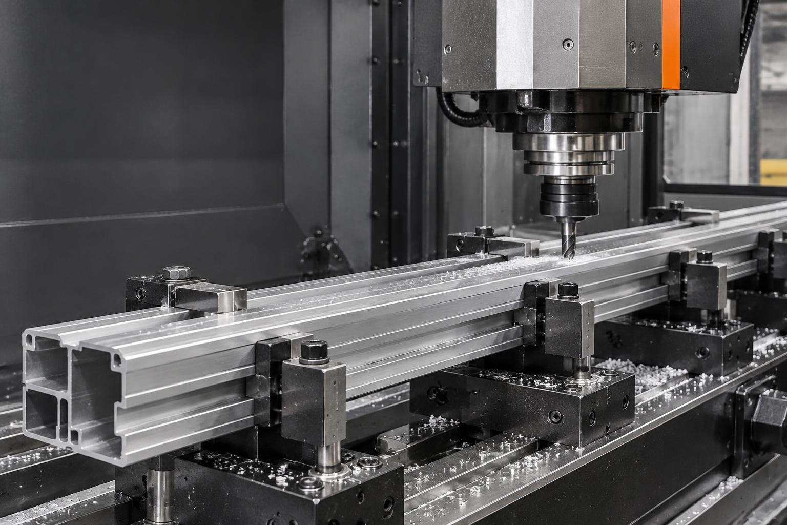
On an extrusion machine, something else joins that chain: the profile itself. Its end. Its orientation. Its straightness and twist. Its position against the stop. The clamp locations. The distance between the cutting zone and the nearest support.
That is why a dimension outside tolerance does not always mean "change the offset." Sometimes an offset is exactly the right correction. Sometimes it is the fastest way to hide the real problem and create the next one.
Conventional VMC
- Machine
- Fixture
- Datum
- Component
- Tool
Extrusion machine
- Machine
- Profile / orientation
- Reference end
- End stop
- Clamps
- Support points
- Datum
- Component
- Tool
Two CNC worlds, two different problems
A conventional machining centre usually starts with a billet, forging, casting or semi-finished part. You locate it in a vice, soft jaws, a fixture or a pallet system, establish the datum with G54 or another work offset, and the machine gradually turns stock into the finished component.
An aluminium extrusion already contains much of the final cross-section: walls, channels, ribs, hollow sections, mounting faces. The CNC machine adds local features such as holes, slots, pockets, cut-outs, threads, countersinks, end machining and milled faces. Those features can be spread across several metres of material.
That changes the whole mindset.
The machines, in numbers
Manufacturer figures make the difference concrete.
Mecal MC307 Falcon (4-axis)
- X rapid: 150 m/min (2.5 m/s), acceleration 3.8 m/s²
- Spindle: up to 24,000 rpm, 8.5 kW
- A axis: ±125° on the versions I worked on (up to ±135° on some)
- Standard working length 4,000 mm, up to 8,000 mm with re-gripping
Mecal MC304 Ariel (4-axis)
- Gantry structure, working length 7,430 mm
- Rapids: X 80, Y 60, Z 40 m/min
- Spindle: up to 20,000 rpm, 8.5 kW, HSK-F63, 12-tool magazine
- A axis: spindle rotation ±90° (180° in total)
- Pendular loading, zero stops at each end
What actually moves changes how you think
On paper the two machines look like cousins. In practice they move differently.
On the Falcon, the spindle travels along the profile on rails. The 4th axis, A, rotates about the profile's longitudinal axis, with a range of ±125° on the versions I worked on. That is 250° in total, and it reaches beyond the vertical side faces.
The Ariel is a gantry. X is not the spindle alone: it is the whole carriage with the spindle inside. Y and Z move the spindle, and the A axis is the spindle itself, tilting ±90°. That lets it machine the top and both sides without turning the material in the clamps, and not only from above like a 3-axis machine.
That has three practical consequences:
- Fewer reclamps. Side features are machined without unclamping the profile. One reference instead of two means fewer chances for a location error.
- A bigger collision envelope. When the A axis turns to a side face, the head body sits beside the profile, exactly where the clamps are. On a 3-axis machine you mostly think about the top. With an A axis you think in 3D.
- What you send towards a clamp. On the Ariel it is a whole carriage, not just a spindle.
Mecal MC307 Falcon
- Spindle travel on rails · X
- A about longitudinal axis · ±125°
Mecal MC304 Ariel
- Whole gantry carriage · X
- Spindle A tilt · ±90°
- Spindle · Y / Z
On an extrusion machine, the datum starts outside the control
On a VMC it is easy to think of the datum as a number inside G54. But G54 does not physically locate anything. It is only a mathematical description of where the control believes the component is.
On the Mecal machines, that relationship is much more physical. The extrusion has to be loaded from the correct end, in the correct orientation, seated against the stop, and then clamped. If something is wrong at that stage, the program can run perfectly and still make the wrong part.
Imagine a hole that should be 250.00 mm from the end of the extrusion. Inspection says 250.30 mm.
The worst reaction is: "Fine, subtract 0.30."
First you need to understand why that 0.30 mm exists. If every feature along the length is shifted by roughly the same amount, I start thinking about the reference. Is the profile actually touching the stop? Is there a chip between them? A burr on the end? Did the material move during clamping? Is it the correct reference end, in the correct orientation?
If the real cause was one chip against the stop, a -0.30 correction makes the next, correctly seated part wrong. The machine does exactly what it is told. The setter gave it an incorrect picture of the physical world.
The end stop is part of the measurement chain
On long-profile machining, the stop is not just a workholding accessory. It is part of the reference chain. A chip, a burr, a damaged saw-cut end or a profile that has not truly seated can all shift the position of every feature machined afterwards. The error does not disappear. It travels with the geometry.
That is the difference between a machining error and a location error. If a pocket is the right size but 0.30 mm too far along the profile, the cutter diameter is not my first suspect. If every feature is shifted by the same amount, even less so.
No flood coolant: air and oil mist
Another thing separates these machines from a typical VMC: there is no flood coolant. The cutting zone is cooled by air, with an oil mist delivered to the point of cut. That changes the process more than it seems.
- Chips are blown away, not washed away. Where they land matters. A chip on the reference surface or at the stop is exactly how a location error is born.
- There is no thermal stabiliser. Flood coolant on a VMC keeps part and machine temperature fairly steady. Here more of the temperature behaviour shows up in the profile and in the machine.
- The mist has to reach the cut. Lubrication is only as good as its delivery.
- The upside: parts come off dry. No coolant film, no washed-off chips hiding on the surface, and an easier measurement.
Ariel: one machine, two working zones
The Ariel's working length is around 7.4 metres, and with pendular loading it can be split into two working zones. One zone machines while the next profile is prepared in the other. Then the roles swap.
That is a different production philosophy from a fixture enclosed in a VMC. You are not only asking "does the program fit?" You are thinking about material flow, spindle movement, clamp positions, safety, and what the operator is doing while the other side of the machine is active.
A clamp has a correct position and two bad ones
A clamp cannot be too close to the machining zone. On the Falcon, X rapid is 150 m/min, which is 2.5 metres every second. A poor clamp position turns a small setup error into a serious crash very quickly. The Ariel is slower in X, 80 m/min or about 1.3 m/s, but what it sends towards a clamp is a whole gantry carriage, so it is not forgiving either. There is no room for "it should probably clear."
And with the A axis turned to machine a side face, the head body sits beside the profile, exactly where the clamps are.
But moving the clamp as far away as possible is also wrong. A longer unsupported span means the profile starts to move: vibration increases, surface finish suffers, and with thin-wall aluminium the difference between good and poor support is substantial.
The rule is not "as far from the cutter as possible." It is: far enough for a safe motion envelope, close enough for process stiffness.
Two Falcons, same machine family, different setup reality. On one, clamps were positioned automatically. On the other, they had to be positioned manually before each setup, using the technical drawing. That made the setter's responsibility very direct. You had to know where features would be machined, what the spindle would do, where support was needed, where a clamp would become a collision risk.
The drawing was not only for final inspection. It helped build the setup safely and rigidly before Cycle Start.
And automatic clamp positioning does not remove the need to think. The machine can put a clamp exactly where the system expects it to be. You still have to understand what the extrusion is doing, where cutting forces act and how long the unsupported span is. Automation removes part of the manual work. It does not remove physics.
01 / End stop
02 / Clamps
03 / Machining zone
- 04 / Support points
- Safe head clearance
- Short unsupported span → stiffness
24,000 rpm is not process capability
The Falcon runs up to 24,000 rpm, the Ariel up to 20,000. That fits aluminium profile machining well: high spindle speeds, aluminium-specific tooling, high feed rates.
But maximum spindle capability is not maximum process capability. You can have plenty of rpm, feed, power and tool capability, and the process still becomes unstable because the extrusion vibrates. Then the limiting factor is not the spindle. It is workpiece stiffness.
A three-metre extrusion does not behave like a block in a vice
On a VMC, a short part sits in a vice with a large contact area and a short distance between cut and support. With a long thin-wall extrusion, the cutter enters material between two support points, and the component itself becomes a long flexible structure. The same feature machined at different positions along the profile can see very different local stiffness.
That is why chatter may appear in one section only. The start of the profile machines perfectly, the middle starts singing, the end is fine again.
"Reduce the rpm" may improve the result, but it does not explain it. Ask why the problem appears there. Clamp spacing? Unsupported span? Tool stickout? Engagement? Runout? Local profile geometry? Resonance? That is much more useful than finding one speed at which the noise temporarily disappears.
You can also clamp an extrusion too hard
Long profiles are not always best held "as hard as possible." A thin wall can deform, the section can change shape, and the part can be correct while clamped and move out of tolerance when the clamps release. This matters most with thin-wall profiles, hollow sections, large cavities and asymmetrical extrusions.
There is a big difference between holding the part and holding the part without changing the part. The second is much harder.
The extrusion itself introduces variation
A profile is not necessarily perfectly straight. It can have bow and twist, wall thickness can vary, and one surface can move relative to another within the limits of the extrusion process.
If you locate from surface A but inspect a critical feature relative to surface B, you need to know how stable the A-to-B relationship is in the raw material. The machine cannot know that the incoming geometry changed between batches. It machines from the reference you give it. A setter has to separate machine capability from incoming material capability.
Measurement: the step people skip
Aluminium expands by roughly 23 µm per metre for every 1 °C. On a 3-metre profile, one degree is about 0.07 mm. A 5 °C difference between the moment of machining and the moment of measuring is about 0.35 mm, more than many tolerances allow, and with nothing wrong with the program or the tool.
So before correcting anything, ask: how was it supported when measured, at what temperature, clamped or released? A measurement that is not reliable cannot justify a correction.
23 µm/m/°C
α · Al
≈ 0.07 mm
3 m × 1 °C
≈ 0.35 mm
3 m × 5 °C
CADCam3D changes how you think about the program
The Mecal machines are programmed in Mecal's own environment, CADCam3D, running on a Windows PC at the machine. In conventional CAM on a VMC, you think in terms of model, stock, WCS, fixture, operation, toolpath, postprocessor and NC code.
On a profile machine the thinking is more feature-oriented. Which profile am I machining? Which face is the feature on? Where along the length? From which direction does the tool approach? How is the profile oriented, where are the clamps, and can the spindle reach the feature without entering a dangerous zone?
The environment helps with exactly that. You see the clamp positions on screen, check the tool against the profile and drag features with the mouse, with a real-time simulation. There is an optional CADLink module for importing STEP or IGES files from external CAD, and a Job Simulator that calculates cycle time and catches programming errors before the physical cycle.
But a simulation knows the model. It does not know about the chip at the stop, the twist in this particular batch of extrusions, or a profile that has not seated. The screen shows the profile you drew. The machine cuts the one you loaded.
That does not make one system more advanced than the other. They solve different problems. Conventional CAM is extremely flexible when creating geometry from raw stock. CADCam3D is built around machining features on long existing profiles.
On a conventional machining centre, corrections are more local
On a VMC, many correction relationships are more obvious.
If the entire component is shifted in X, look at workholding, datum, fixture and G54. If only a 20.000 mm pocket has become 19.940 mm, look at the cutter: wear, effective diameter, deflection, CAM. If every depth from one tool is 0.15 mm too shallow, look at that tool's length and correction. If every tool is 0.15 mm too high, the problem looks completely different.
A setter has to separate part location from tool geometry. Moving G54 does not fix an undersize pocket, and changing cutter wear does not fix a component whose datum is shifted.
The trend may matter more than the error
Suppose the width of an external feature goes:
20.00, 20.01, 20.02, 20.04, 20.06, 20.08
Something is evolving: tool wear, thermal growth, increasing runout, worsening chip evacuation.
Now look at this sequence:
20.00, 20.01, 20.00, 20.01, 20.18, 20.19
That tells a different story. What happened between those two parts? A new extrusion? A reclamp? A different stop? A tool change, a restart, a minor crash, a chip under the reference?
A good setter does not only ask how much the error is. They ask how it appeared. A trend and a sudden shift are two different process signatures.
If the first component is wrong, I suspect the setup: datum, program, tool data, orientation, stop, clamp positions. If the first ten are correct and then the dimension starts moving, I look at tool wear, thermal behaviour, chip packing, changing cutting load, holder condition. One part is wrong versus the process is moving. React to both the same way and you end up chasing the dimension instead of controlling the process.
Gradual trend
Dimension (mm) · 20.00–20.20
- Part 120.00
- Part 220.01
- Part 320.02
- Part 420.04
- Part 520.06
- Part 620.08
Sudden shift
Dimension (mm) · 20.00–20.20
- Part 120.00
- Part 220.01
- Part 320.00
- Part 420.01
- Part 520.18
- Part 620.19
Proof-out is different too
On a VMC I watch the fixture, vice, holder clearance, tool length, rapids, active modes and travel limits. On a long profile machine I also have the end stop, the orientation, clamp locations, the full motion envelope across several metres, changing support distance, and a spindle path that looks harmless on screen but passes through a clamp zone.
You do not want to discover a clamp is 50 mm too close while the spindle is already travelling towards it. Positioning clamps by hand on one of the Falcons was not a formality. It was part of the proof-out.
The simulation is the first line of proof-out. It is not the last.
Six situations where I would not touch the offset first
- Every feature along the profile is shifted by +0.50 mm. Check the stop, seating and reference first. Cutter wear does not shift all otherwise-correct geometry by the same amount.
- Only one pocket is gradually becoming undersize. Look at the cutter, effective diameter, wear and deflection. Do not move the global datum.
- The second half of the extrusion shifts after reclamping. Investigate repositioning repeatability. Do not edit every feature individually.
- One tool machines every depth 0.15 mm too shallow. Check tool length, seating and the active correction.
- Chatter appears only in the middle of a long extrusion. Check support, clamp position and local dynamics. Do not automatically cut the whole program's parameters.
- The machine is correct when cold but drifts after two hours. Look for thermal correlation in the profile, the machine and the room. Do not enter random corrections every 20 minutes.
Not every problem should be offset out
Offsets are powerful, but only when they correspond to the real cause. If the cutter is wearing, wear compensation may be right. If tool length is wrong, correct tool length. If the work offset is wrong, correct the datum.
But you do not offset out vibration. You do not fix a clamp that deforms a thin wall with geometry compensation. You do not fix a chip between the profile and the stop by changing the program.
A good correction compensates a known mechanism. A bad correction hides an unexplained one.
What changed physically?
- 01All features shifted → reference / location
- 02One size changes → tool geometry
- 03One tool’s depths change → tool length
- 04Drift / chatter / unreliable result → thermal, vibration, measurement
Known cause → matching correction; unknown cause → investigate
What transfers between both worlds
After years on profile machines and then working with more conventional machining logic, the biggest lesson is not which system uses CADCam3D and which uses G54 or conversational programming. It is the thinking sequence:
REFERENCE → TOOL → WORKHOLDING → MACHINE STATE → PROCESS FORCE → MEASUREMENT → CORRECTION
Is the physical reference correct? Is the tool what the program thinks it is? Is the component where the control assumes? Is it held without distortion? Are the cutting forces moving the tool or the component? Is the measurement itself reliable?
Only then: what do I correct?
Finding the offset table is the easy part. The real skill starts with a different question. When I see 0.20 mm out of tolerance, I do not ask "which number can I change?" I ask: "What physically changed by 0.20 mm?"
Good CNC machining is not about moving numbers until the gauge turns green. It is about understanding what those numbers represent on the real machine. Whether it is a Mecal Falcon, an Ariel, a Mazak running Mazatrol or a conventional machining centre on FANUC, the machine changes. The control changes. The workholding changes. The logic of a good setter does not.
What is the strangest real cause of a 0.2 mm error you have ever found?
Related articles & technical topics
Soft Metal, Hard Lessons
What machining aluminium extrusions really takes — datums, support, deformation, measurement and finishing treated as one process.
Article in English
Read on LinkedIn