CNC / ALUMINIUM / CHIP EVACUATION
Clear the Chips or Recut Them: Why Chip Evacuation Matters When Milling Aluminium
Mateusz Żuławski
CNC Programmer Setter Operator at Newby Foundries
≈ 5 min read
High-helix, 2-flute end mills are designed to provide chip space and support efficient evacuation. But if chips remain in the cutting zone, the cutter may end up machining them again.
When machining aluminium, chip evacuation is not a secondary detail. It is part of the cutting process.
Aluminium can produce long, continuous or sticky chips. If those chips cannot leave the cutting zone efficiently, they may become trapped between the tool, workpiece and flute gullets.
The result can be chip recutting, rubbing, increased heat, poor surface finish and reduced tool life.
The objective is simple: remove chips from the cutting zone before they can interfere with the next cutting engagement.
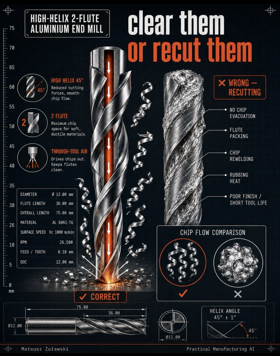
1. Why a 2-flute end mill for aluminium?
A 2-flute end mill generally provides larger flute gullets than a comparable tool with more flutes.
That additional space can help when machining soft, ductile materials such as aluminium.
A high-helix geometry can also support smoother chip flow and reduce cutting forces in suitable applications.
The infographic uses a 45° helix as its example. This is a tool geometry specification, not a universal optimum for every aluminium operation.
The correct choice still depends on:
- Aluminium alloy and temper.
- Tool diameter and flute length.
- Radial and axial engagement.
- Cutting speed and feed per tooth.
- Tool overhang and setup stiffness.
- Available chip evacuation and air delivery.
2. What happens when chips cannot escape?
When chips remain in the cutting zone, several problems can develop.
No effective chip evacuation
Chips stay near the cutting edges instead of leaving the machining area.
Flute packing
Chips accumulate in the flute gullets, reducing the available space for newly generated material.
Chip recutting
The tool may encounter chips that have already been removed. These can be cut again, crushed or trapped against the workpiece.
Rubbing and heat
Poor chip evacuation can increase friction and heat, particularly when chips become trapped between the tool and the workpiece.
Poor finish and shorter tool life
Repeated chip contact and unstable cutting conditions can damage the surface and accelerate tool wear.
These effects are related, but their severity depends on the actual cutting conditions and the toolpath.
3. Through-tool air and chip evacuation
The infographic illustrates air delivered through the tool.
Where the tool and machine are designed for it, through-tool air can help drive chips out of deep or enclosed cutting areas and keep flute spaces clearer.
However, air delivery must be suitable for the operation.
Consider:
- Air pressure and flow.
- Nozzle or through-tool delivery direction.
- Pocket depth and geometry.
- Chip size and shape.
- Toolpath and cutting engagement.
- Whether chips have a clear exit route.
Air does not automatically solve every chip evacuation problem. In some applications, external air blast, coolant or a different toolpath may be more appropriate.
The important point is that chips need somewhere to go.
4. Understanding the example tool specifications
The infographic shows the following example:
| Parameter | Example value |
|---|---|
| Tool diameter | 12.00 mm |
| Flute length | 36.00 mm |
| Overall length | 75.00 mm |
| Material | Al 6061-T6 |
| Cutting speed | 1,000 m/min |
| Spindle speed | 26,500 rpm |
| Feed per tooth | 0.10 mm |
| Depth of cut | 12.00 mm |
| Helix angle | 45° ± 1° |
These values describe the illustrated example, not a universal cutting recipe.
For a 12 mm diameter cutter at 1,000 m/min:
n = (Vc × 1000) / (π × D)
n = (1000 × 1000) / (π × 12)
n ≈ 26,526 rpm
The infographic rounds this to approximately 26,500 rpm.
For a 2-flute cutter at 0.10 mm per tooth:
Vf = n × z × fz
Vf = 26,500 × 2 × 0.10
Vf = 5,300 mm/min
The actual cutting data must be checked against the tool manufacturer’s recommendations, spindle limits, machine capability, tool engagement, workholding and chip evacuation conditions.
The 12 mm depth-of-cut value also needs to be interpreted in the context of the actual operation: axial depth and radial engagement are not interchangeable.
5. Why high helix and flute geometry matter
The helix angle influences the way the cutting edge enters and leaves the material.
A high-helix tool can provide smoother cutting action and encourage chip movement along the flutes.
But a high helix is not automatically better in every situation.
The tool must also have sufficient core strength, suitable edge geometry and adequate support from the holder and machine.
A good tool choice balances:
- Chip space.
- Cutting-edge strength.
- Cutting forces.
- Surface finish.
- Tool stiffness.
- Material behaviour.
6. Practical habits for better chip evacuation
01 — Keep the cutting zone clear
Choose an appropriate chip evacuation strategy. Make sure chips can leave the pocket or machining area rather than accumulating around the tool.
02 — Use the right toolpath
Avoid toolpaths that repeatedly drive the cutter into trapped chips. Consider engagement, entry direction and where the chips are being pushed.
03 — Control tool overhang
Use the shortest practical tool assembly. Excessive overhang reduces stiffness and can increase deflection and vibration.
Final takeaway
A cutter does not only need to remove material. It also needs to move the resulting chips away from the cutting zone.
A 2-flute, high-helix end mill can be a useful choice for aluminium because its geometry provides substantial chip space and supports chip evacuation.
But even a suitable cutter can produce poor results when chips become trapped and are recut.
Clear the chips. Keep the flutes open. Give the cutting process room to work.
Question for CNC machinists:
When machining deep aluminium pockets, do you prefer through-tool air, external air blast or coolant — and what makes the biggest difference in your setup?
#CNC #AluminiumMachining #EndMills #ChipEvacuation #Machining #PracticalManufacturingAI