CNC / TOOLING / END MILLS
The Machinist’s Guide to End Mills: How to Choose the Right Cutter
Mateusz Żuławski
CNC Programmer Setter Operator at Newby Foundries
≈ 5 min read
2 flutes, 4 flutes or 6 flutes? Understanding chip evacuation, cutting geometry and the parameters that influence tool life.
Choosing an end mill is not simply a matter of selecting the correct diameter.
The number of flutes, flute geometry, helix angle, substrate, coating, tool overhang and cutting conditions all influence how the tool behaves.
A cutter that performs well in aluminium may be a poor choice for stainless steel. A tool designed for finishing may not provide enough chip space for aggressive roughing.
Understanding these differences helps you select the right tool for the material and the operation.
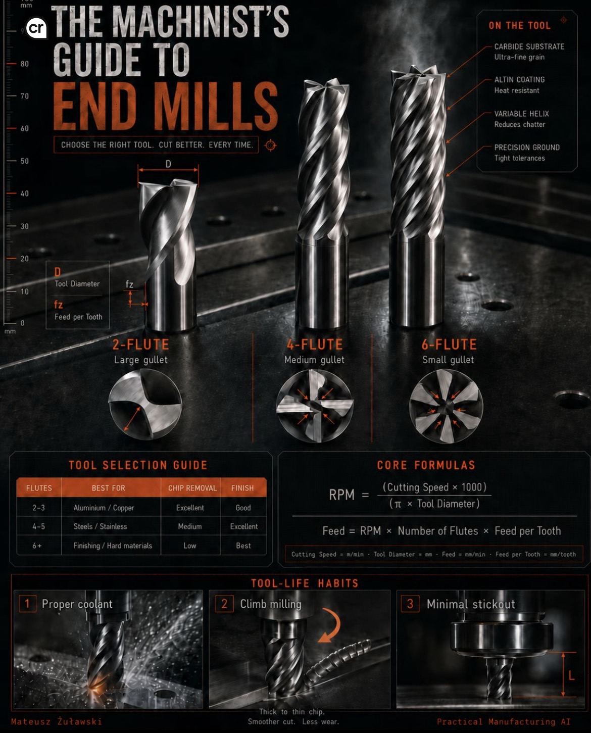
1. Why does flute count matter?
The number of flutes affects the available space for chip evacuation and the number of cutting edges participating in the operation.
As a general starting point:
2-flute end mills — large chip gullets
Often suitable for aluminium and copper, where efficient chip evacuation is important.
The larger gullets provide more room for chips, particularly when machining materials that can produce long or sticky chips.
4-flute end mills — medium chip gullets
A common choice for steels and stainless steels.
They provide more cutting edges while retaining a practical balance between chip space and tool strength.
6-flute end mills — smaller chip gullets
Often used for finishing and selected hard-material applications.
The additional cutting edges can support higher feed rates when the process, tool geometry and machine capability allow it. However, reduced chip space requires appropriate engagement and chip evacuation.
These are general selection guidelines, not universal rules. The manufacturer’s recommended application and the actual tool geometry should always take priority.
2. What should you look for in the tool itself?
The cutting performance depends on more than the number of flutes.
Carbide substrate
Fine-grain carbide provides the basis for hardness, wear resistance and cutting-edge stability.
AlTiN coating
Aluminium titanium nitride coatings are designed for demanding thermal conditions and can improve performance in suitable applications. Coating selection must match the material and cutting conditions.
Variable helix
Variable helix geometry can help reduce regenerative chatter by disrupting regular excitation patterns.
It does not eliminate vibration in every setup. Workholding, tool overhang, engagement and machine stiffness still matter.
Precision-ground geometry
Accurate grinding and controlled tolerances help maintain predictable cutting geometry and tool performance.
3. Chip evacuation: do not ignore the gullets
The flute gullets provide space for chips to move away from the cutting zone.
When chip volume becomes too high for the available space, chips can recut, pack into the flutes or interfere with the cutting process.
This can increase heat, damage the cutting edges and reduce tool life.
That is why a two-flute cutter can be a better choice for some aluminium operations than a six-flute cutter, even when the latter has more cutting edges.
The goal is not simply to maximise flute count. It is to balance cutting-edge engagement, chip space and process stability.
4. Core cutting formulas
For metric cutting calculations:
Spindle speed
n = (Vc × 1000) / (π × D)
Where:
- n = spindle speed [rpm]
- Vc = cutting speed [m/min]
- D = tool diameter [mm]
Feed rate
Vf = n × z × fz
Where:
- Vf = feed rate [mm/min]
- n = spindle speed [rpm]
- z = number of flutes
- fz = feed per tooth [mm/tooth]
The formulas provide the calculated starting values. Always check the manufacturer’s recommended cutting data, machine limits, tool engagement and actual process conditions.
5. Three habits that help extend tool life
01 — Use appropriate coolant or lubrication
The coolant strategy must suit the material, tool and operation.
Its purpose may include cooling, lubrication and chip evacuation. Follow the tool manufacturer’s recommendations and the machine’s operating procedures.
02 — Consider climb milling
Climb milling can provide favourable chip formation and surface finish in suitable conditions.
It requires a sufficiently rigid setup and a machine with appropriate backlash control. Conventional milling may be preferable in some circumstances.
03 — Keep tool overhang to a minimum
Longer tool overhang reduces stiffness and increases the risk of deflection and vibration.
For a cantilever-like tool system, deflection can increase very rapidly as unsupported length grows. Avoid unnecessary stickout and use the shortest practical tool assembly.
6. The practical takeaway
A good end mill is not simply the one with the most flutes or the highest advertised cutting speed.
It is the tool whose geometry, substrate, coating and flute count match the material, operation and machine conditions.
Before changing cutting parameters, consider:
- Material and hardness.
- Number of flutes and available chip space.
- Tool diameter and flute geometry.
- Cutting speed and feed per tooth.
- Tool overhang and workholding stiffness.
- Coolant and chip evacuation.
- Machine capability and process stability.
Choose the right tool. Give the chips room to escape. Keep the setup rigid.
That is a much better starting point for consistent machining and longer tool life.
Question for CNC machinists:
When machining aluminium, do you prefer a 2-flute or 3-flute cutter — and what makes you choose one over the other?
#CNC #Machining #EndMills #Tooling #Manufacturing #PracticalManufacturingAI