Skip to content

10 / Practical Manufacturing AI

Free Manufacturing Resources

A practical knowledge library for CNC operators, setters, machinists and manufacturing professionals. English and Polish PDFs — free, with no registration, paywall or email capture.

Flagship · Self-study course

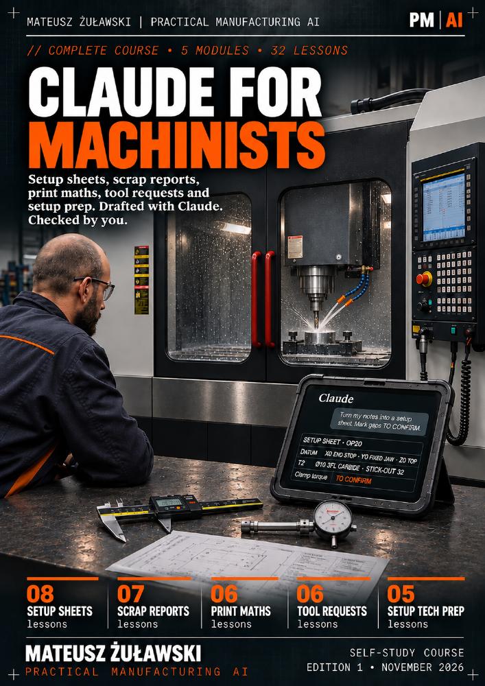
Claude for Machinists

Use Claude to draft useful production documents from clear, anonymised job information. Work through prompts and real-job exercises, then verify every output against the actual job.

5 modules / 32 lessonsAbout 15 minutes per lessonPrompts + real-job exercises

About 6.5 weeks at one lesson per working day

A practical document pack — not a certificate.

Build a setup-sheet template, a scrap report, a calculation sheet, a tool request and a shift handover note from your own jobs. Review and adapt this practical pack for real work.

Free · No paywall

Document language

33 pages · PDF · English

Original cover of Claude for Machinists by Mateusz Żuławski
By Mateusz Żuławski · Practical Manufacturing AI

Five modules. One practical pack.

  1. 01

    Setup Sheets

    Capture the setup, tooling and checks in a clear handover.

    8 lessons
  2. 02

    Scrap Reports

    Turn job facts into a traceable scrap report.

    7 lessons
  3. 03

    Print Maths

    Work through drawing calculations and check the numbers.

    6 lessons
  4. 04

    Tool Requests

    Draft clear tool requests from verified requirements.

    6 lessons
  5. 05

    Setup Tech Prep

    Organise the technical information needed before a setup.

    5 lessons

Technical visual guide · Not a course

A Practical Map of CNC Machine Types

This guide explains why machine selection should follow part geometry, material, tolerances, size, access and production volume. It is an orientation map for initial process selection, not a substitute for detailed process planning.

12 slides · Free · No paywall

Slide 1 / 12

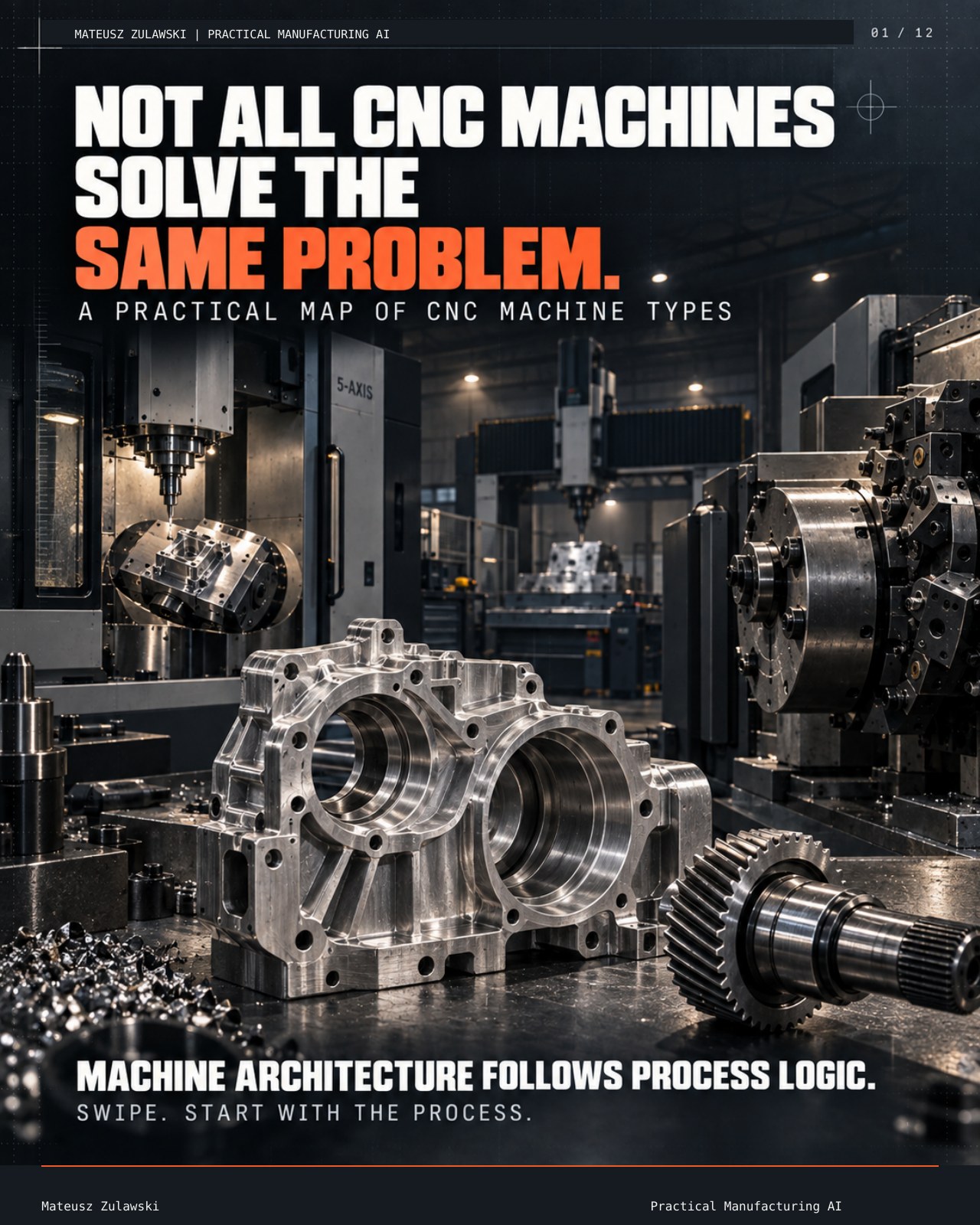
Cover — not every machine solves the same problem

The opening slide introduces the central idea: machine architecture follows process logic. Similar automation does not mean identical kinematics, stiffness, tool access or production economics. Define the manufacturing task before selecting the platform.

Document language

12 pages · PDF · English

All slide descriptions
  1. 01Cover — not every machine solves the same problem

    The opening slide introduces the central idea: machine architecture follows process logic. Similar automation does not mean identical kinematics, stiffness, tool access or production economics. Define the manufacturing task before selecting the platform.

  2. 02Start with the process, not the machine

    The milled housing, turned shaft, gear, sheet profile and EDM feature represent different geometric and material requirements. A more complex machine is not automatically better if a simpler one can produce the part more accurately, quickly or economically. Selection should follow the component and the complete process.

  3. 0301 — Milling: the same process, different architectures

    A VMC has a vertical spindle and suits many prismatic parts. An HMC supports multi-face machining and chip evacuation. A gantry/double-column machine provides a large envelope and rigidity for large components. The slide also introduces five-axis kinematics: three linear and two rotary axes, used indexed or simultaneously.

  4. 0402 — Turning: when the part rotates

    A turning centre rotates the workpiece for shafts, bushes, flanges and pins. A mill-turn machine combines turning and milling, reducing setups on complex parts. A Swiss-type automatic with a sliding headstock suits long, slender, small-diameter components. The key question is what should rotate to produce the geometry efficiently.

  5. 0503 — Holemaking: sometimes less is faster

    A drilling and tapping centre specialises in fast axial operations. Quick tool changes, spindle acceleration and short auxiliary times can be advantageous when drilling and tapping dominate. The drill–tap–ream sequence highlights that a larger machine’s flexibility does not necessarily produce a shorter cycle.

  6. 0604 — Gear generation

    The slide compares hobbing, shaping and power skiving. Tooth geometry is generated through coordinated tool/workpiece motion, but each method uses different kinematics. Spur gears, helical gears and splines depend on controlled relative motion, not simply milling a tooth-shaped outline.

  7. 0705 — EDM: no tool contact

    EDM removes material through controlled electrical discharges rather than conventional cutting contact. Wire EDM uses a moving wire electrode for through profiles; sinker EDM uses a shaped electrode for cavities and blind features. Electrical conductivity—not hardness alone—is the process requirement.

  8. 0806–07 — Plate routing and thermal cutting

    The slide compares mechanical routing with laser, plasma and oxy-fuel cutting. They differ in material-removal mechanism, suitable materials, edge quality and heat input. Laser uses a focused beam, plasma cuts conductive metals, and oxy-fuel is associated mainly with carbon steel. Abrasive waterjet is also noted as an option without a heat-affected zone.

  9. 0908 — Abrasive machining

    Grinding is a distinct process stage, not merely a cosmetic pass after milling or turning. It controls dimensional accuracy, form and surface condition, particularly for tight tolerances and hardened surfaces. When microns and surface integrity matter, the process choice changes.

  10. 10Do not ask which CNC is best

    The slide maps typical geometries to platforms: prismatic parts to VMC/HMC/five-axis machines, large parts to gantry machines, rotational parts to turning, hole-dominated work to drilling/tapping centres, and gears to dedicated gear processes. It then distinguishes EDM, routers, thermal cutting and grinding by material and geometry. This is a shortlist for starting an analysis, not a finished process decision.

  11. 11The best machine is not the one with the most axes

    Axis count alone does not determine quality or productivity. Geometry, stiffness, access, workflow, workholding and cycle time all matter. Different machines have different strengths, but the goal is the same: an accurate part produced through a stable, economical process.

  12. 12The complete CNC machine-type map

    The final slide gathers VMC/HMC/five-axis/gantry machines, turning and mill-turn, Swiss-type automatics, drilling/tapping centres, gear generation, EDM, routers, laser, plasma, oxy-fuel and grinding. The lower table links typical parts to suggested platforms. It is a quick reference for initial process planning.
Technical visual guide · Not a course

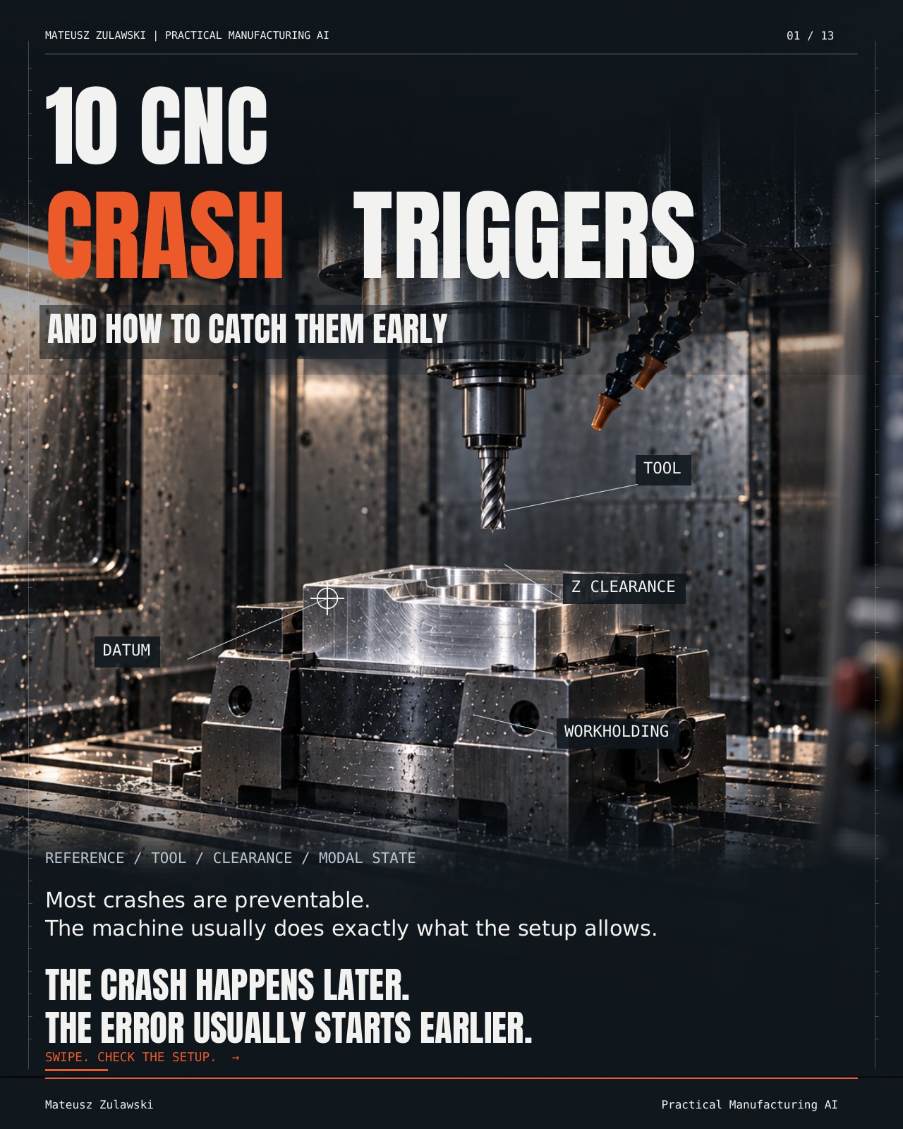
10 CNC Crash Triggers and How to Catch Them Early

This carousel covers ten sources of CNC crashes or unsafe motion and identifies checks to make before movement. Its central message is that a crash is usually the final result of an earlier error in the datum, compensation, tool, modal state, clearance, workholding or prove-out. The examples are Fanuc-style ISO milling illustrations; actual behaviour depends on the control, machine and approved procedures.

13 slides · Free · No paywall

Slide 1 / 13

Cover — the error starts earlier

The four areas—datum, tool, Z clearance and workholding—show why the program alone cannot establish safety. The actual positions of the part, tool and clamps, plus the active control state, must be known. Many crashes can be prevented by checking the setup before Cycle Start.

Document language

13 pages · PDF · English

All slide descriptions
  1. 01Cover — the error starts earlier

    The four areas—datum, tool, Z clearance and workholding—show why the program alone cannot establish safety. The actual positions of the part, tool and clamps, plus the active control state, must be known. Many crashes can be prevented by checking the setup before Cycle Start.

  2. 0201 — Wrong active work offset

    The program expects fixture B and G55, but G54 remains active. Coordinates may be correct while the path is shifted to the wrong origin. Explicitly call the required work offset and verify its active status and values before motion.

  3. 0302 — Datum set on the wrong reference

    The example uses a Ø10 edge finder with a 5.0 mm radius. Taking zero from the tool axis instead of the edge, or omitting radius correction, creates a datum error that shifts the job. The illustration shows a left-edge touch-off; the sign depends on approach direction. Verify the reference surface and cross-check a known feature.

  4. 0403 — Tool-length compensation

    At the same spindle Z position, two tools can have different tip positions if compensation is missing or incorrect. G43 H05 is shown as something to verify, not as a ready-to-run start block. Check T↔H, the offset value and the actual control state; automatic activation varies by control.

  5. 0504 — Rapid below clearance

    The example marks Z+60 as safe, Z+45 as the clamp height and Z+30 as too low for the illustrated setup. An XY rapid can cross the clamp if Z is not retracted first. The suggested sequence is retract Z, move XY, then approach Z at a clear location. Check the full tool-and-holder envelope.

  6. 0605 — Jog and handwheel error

    A crash can occur without an NC program. The panel shows X/Y/Z, ×1/×10/×100 increments and a separate rapid override. The operator must know the actual distance per click, axis and direction; rapid override may not limit MPG movement. Use the smallest suitable increment.

  7. 0706 — Modal leftovers and restarts

    G91, G41, G81 and G95 are examples of states that may remain active. Restarting from an arbitrary line can skip blocks that establish the tool and modes. The slide lists G17, G40, G49, G80, G90 and G94 as example states and reminds that G49 cancels tool-length compensation. Avoid blind resets and use the approved restart routine.

  8. 0807 — Wrong tool or holder

    The program may call T12 while a different tool, such as T08, is physically in the spindle. Different diameter, length and holder change the assembly envelope and clearance. Verify the physical tool against T#, inspect the holder, M03/M04 and required RPM.

  9. 0908 — Feed mode and units

    An F value or coordinate can be dangerous if G94/G95 and G20/G21 are ignored. The slide shows F0.05 in G94, F400 in G95 and X100 under G20, plus mm/min = mm/rev × RPM. Check mode, units and value plausibility before entry; do not rely on a control alarm.

  10. 1009 — No prove-out

    The sequence is simulation, air run, single block and the first controlled cut. Simulation is only as reliable as its model and setup data. The slide warns against a generic Z+100 shift and recommends an approved air-run method plus checks of travel, return moves and offsets.

  11. 1110 — Poor workholding

    Chips, weak jaw contact or clamp interference can let the part shift or lift under cutting forces. Clean and seat the part, use approved torque and check contact and clearance. A manual tug test does not prove resistance to real cutting loads.

  12. 12Pre-flight checklist before Cycle Start

    Seven checks cover datum, tool length, tool/spindle, modal state, clearance, workholding and prove-out. Items include T↔H, M03/M04, RPM, G17/G40/G49/G80/G90/G94 and G20/G21. Examples are Fanuc-style ISO milling references; other controls and lathes may behave differently. The machine manual and approved procedures govern.

  13. 13Bonus — the full crash-trigger map

    The slide brings all ten crash triggers and their checks together in one overview. The pre-flight list appears again, making the page useful as a quick reference before starting a cycle. The aim is to find the setup cause before editing the program or running the machine.

Technical visual guide · Not a course

GD&T for CNC Manufacturing — Reading the Geometry

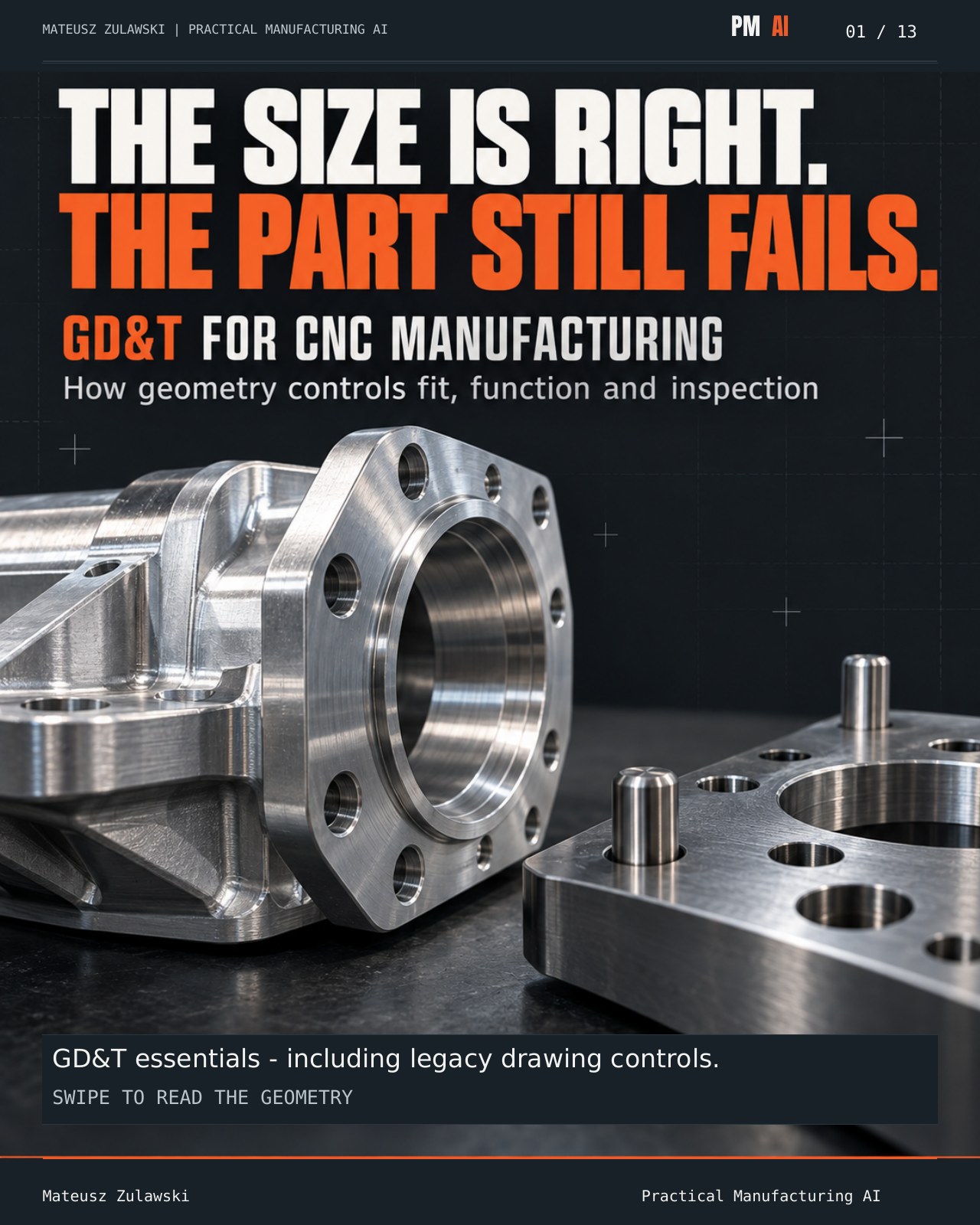
This guide shows why correct size does not guarantee an acceptable part if location, orientation, form or runout requirements relative to datums are not met. It covers 3-2-1 location, position, orientation, perpendicularity, straightness, flatness, circularity, cylindricity, profile, runout, legacy ASME controls and measurement selection. The standard and edition referenced by the drawing must always govern.

13 slides · Free · No paywall

Slide 1 / 13

Cover — the size is right, but the part still fails

A component can have the correct size and still fail to fit or function. Conformity also depends on location, orientation and form relative to datums and drawing requirements. The carousel introduces practical GD&T interpretation, including legacy callouts.

Document language

13 pages · PDF · English

All slide descriptions
  1. 01Cover — the size is right, but the part still fails

    A component can have the correct size and still fail to fit or function. Conformity also depends on location, orientation and form relative to datums and drawing requirements. The carousel introduces practical GD&T interpretation, including legacy callouts.

  2. 02The reference comes first — illustrative 3-2-1

    Primary datum A uses three support contacts, secondary B uses two side contacts, and tertiary C uses one end contact. The sequence constrains degrees of freedom and affects part evaluation. Locators are shown without clamps, and the slide notes that not every datum scheme is 3-2-1.

  3. 03Position — where the feature belongs

    Position controls the location of a hole axis or centre plane relative to theoretically exact dimensions, a tolerance zone and datums. The illustrated zone is cylindrical and the actual axis must fit within it. A hole may have the correct diameter but the wrong location; modifiers may affect the available tolerance.

  4. 04Orientation — the angle needs a reference

    Parallelism, perpendicularity and angularity constrain direction relative to datum A. They control orientation within a defined zone but do not establish feature location by themselves. A correct angle therefore does not automatically mean correct location.

  5. 050.05 is not an angle — perpendicularity

    The 0.05 value in a perpendicularity callout is a tolerance-zone length, not an angle of 0.05°. The correct callout defines two parallel planes 0.05 mm apart and perpendicular to datum A. The entire specified surface must be evaluated, not just one angle reading.

  6. 06Straightness and flatness

    Straightness controls a line element fitting between two parallel lines. Flatness controls an entire surface between two parallel planes. The slide notes that axis straightness uses a different zone and that these form controls do not reference a datum by themselves.

  7. 07Circularity and cylindricity

    Circularity evaluates each circular section between two concentric circles. Cylindricity evaluates the whole surface between two coaxial cylinders. A correct section does not prove the form of the entire cylinder; size limits remain a separate requirement.

  8. 08Profile — a contour needs a tolerance zone

    Profile of a line controls the contour in specified sections; profile of a surface controls the entire specified surface. The illustrated zone is a band around the nominal shape, while its disposition is defined by the drawing. Datums can constrain the zone’s orientation and location.

  9. 09Runout — geometry during rotation

    Circular runout evaluates each specified circular element during rotation; total runout evaluates the entire specified surface. A single indicator reading cannot describe the whole surface. Between-centres inspection is valid only when it establishes the required datum axis; the example is radial.

  10. 10Legacy drawings — concentricity and symmetry

    Concentricity relates median points to a datum axis; symmetry relates median points to a datum centre plane. The slide notes their removal from ASME Y14.5-2018, but the edition referenced by an older drawing still governs its interpretation. Changes require engineering approval; ISO GPS has its own rules.

  11. 11Different failures need different first checks

    If all holes are shifted, check the datum, seating and coordinate system. If one bore is undersize, check the tool, compensation and cutting behaviour. If runout is excessive, inspect datum establishment and surface geometry. The failed requirement guides diagnosis; an offset cannot remove every cause.

  12. 12The measurement must match the requirement

    A convenient reading may not evaluate the geometry specified on the drawing. The example shows that a probe approach position is not a measuring contact; the bore must be sampled around its circumference and at multiple heights. Define the feature, datum, zone and sampling strategy, then validate uncertainty, calibration, contact and conditions. More digits do not prove conformity.

  13. 13Save the geometry map

    The slide groups controls into form, orientation, location, profile and runout. It lists straightness, flatness, circularity, cylindricity, parallelism, perpendicularity, angularity, position, profile of a line and surface, and circular and total runout. Legacy ASME concentricity and symmetry are listed separately, with a reminder to check the drawing standard and edition.

Visual explainer · Not a course

How G-Code Taught Machines to Move

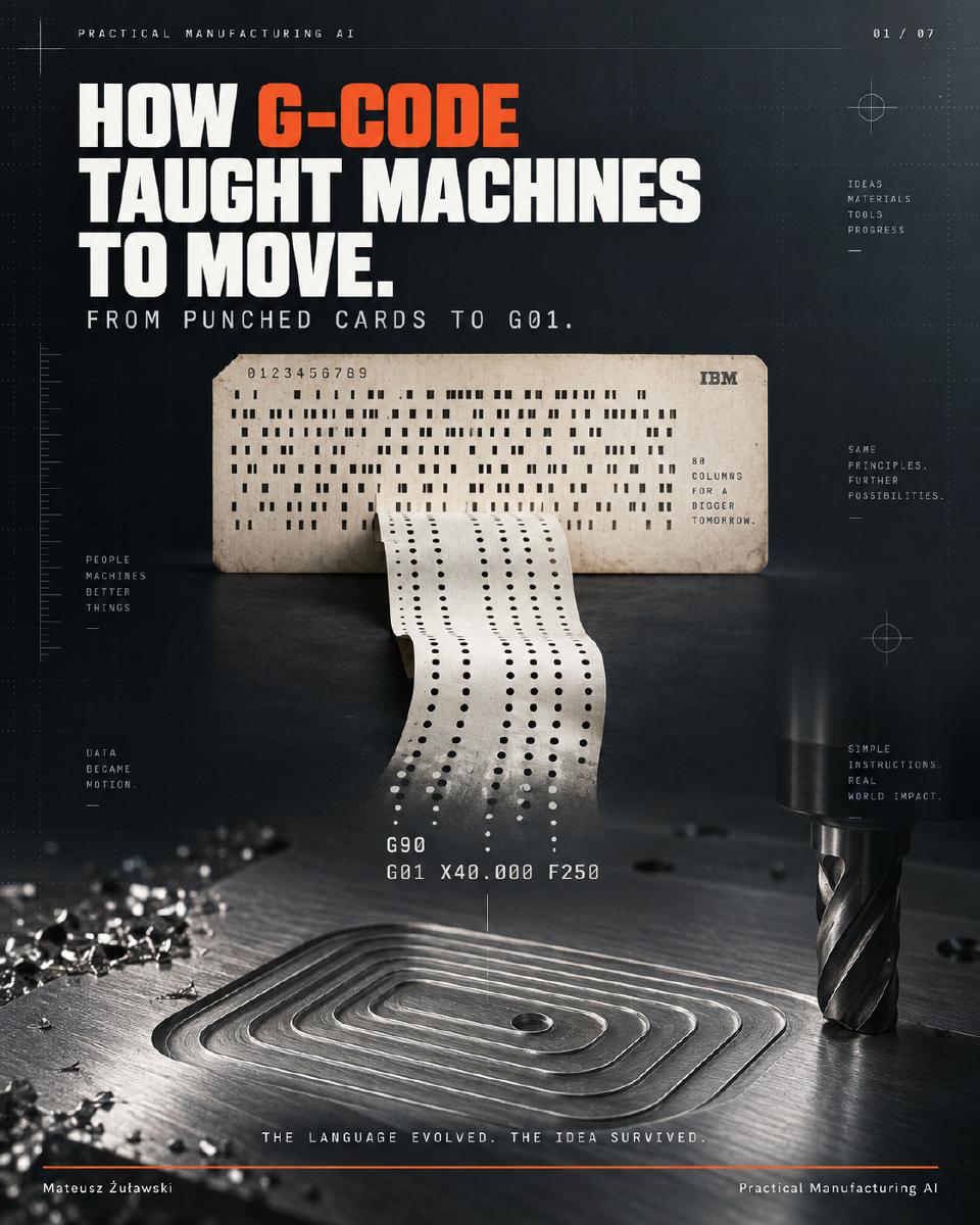
For CNC professionals and curious readers: follow punched-card calculations, John T. Parsons and Frank Stulen, MIT and U.S. Air Force NC milling, APT, EIA RS-274 (1963) and modern CNC. See how the route from an idea to machine motion evolved.

The language evolved. The idea survived.

7 carousel slides · 8-page PDF in each language · Free · No paywall

Slide 1: From punched cards to G01

Slide 1 / 7

From punched cards to G01

The language evolved. The idea survived. Follow the path from stored instructions to controlled motion.

Document language

8 pages · PDF · English

Mateusz Żuławski / Practical Manufacturing AI

Knowledge built around real work

Mateusz Żuławski creates Practical Manufacturing AI resources for manufacturing professionals: practical documentation, clear technical explanations and AI used as support — never as a substitute for machining knowledge.